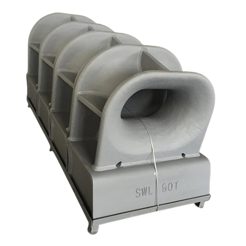
ISO 13713 Mooring Chock
- Type: ISO 13713 Mooring Chock Type A & Type B
- Material: Cast steel (per ISO 13713), ductile iron optional.
- Size Range: Available in multiple sizes from 150mm to 500mm (inside opening).
- Weight: 48KG to 396KG
- Surface Treatment: Primer coated, marine paint, or hot-dip galvanized.
- Welding Type: Base or bulwark-mounted (as per design).
- Certificate: CCS, DNV, ABS, BV, LR, etc.
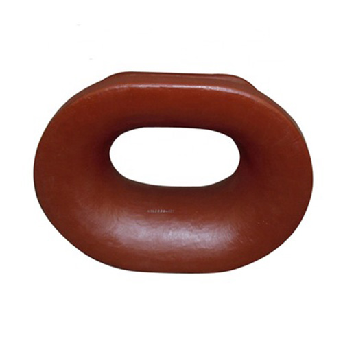
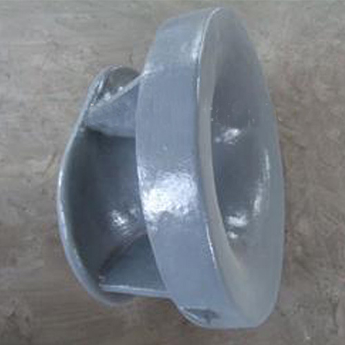
The ISO13713 Mooring Chock is a heavy-duty marine deck fitting, available in two types: Type A and Type B. It is designed in accordance with the International Standard ISO 13713, ensuring global compliance and performance. Typically welded to the deck or bulwark of ships, this closed chock provides a smooth, reinforced guide for mooring ropes, reducing abrasion and ensuring secure and safe berthing operations.
The ISO13713 Mooring Chocks are normally adopted for ships which use nylon or other synthetic ropes other than wire ropes considering the small bending ratio. Built to withstand the harsh marine environment, this chock is an essential component for any seagoing vessel. Its robust construction and streamlined interior design make it a critical component in ship mooring systems across commercial, industrial, and military marine vessels.
As a leading supplier of marine equipment, Boomarine offers a wide range of mooring chocks to suit your every need. Contact us today to learn more about our range of ISO 13713 compliant mooring chocks and find the perfect solution for your vessel’s needs.
ISO 13713 Mooring Chock Dimensions:
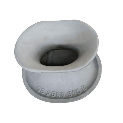
Dimensions of Type A – Deck-mounted mooring chocks
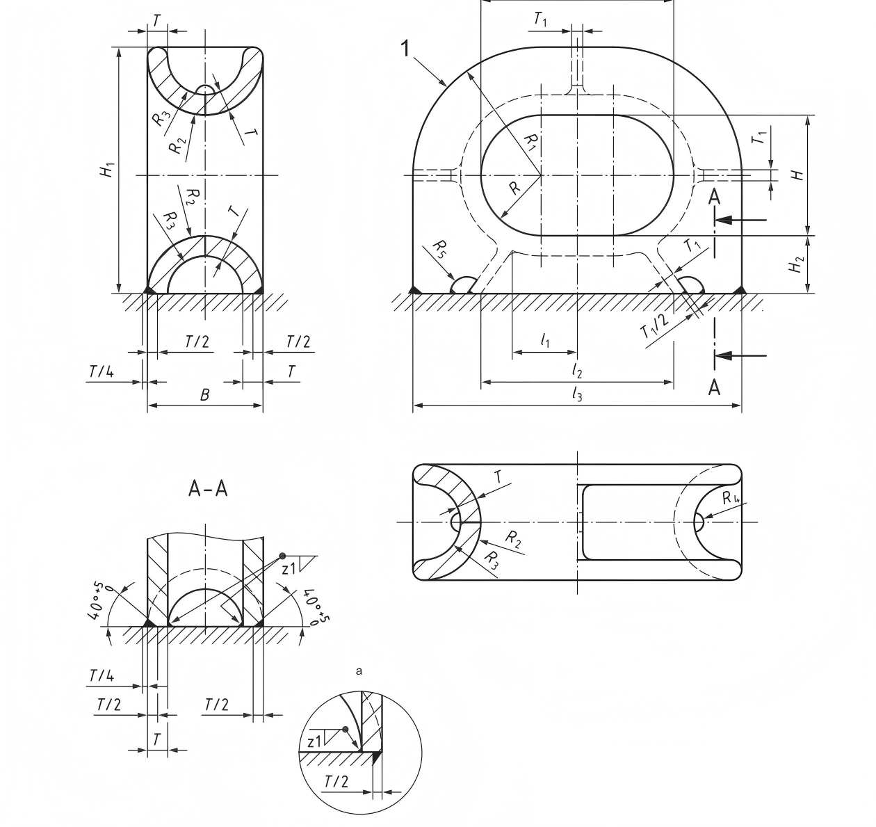
| Nominal size L×H (mm) | l₁ | l₂ | l₃ | B | H₁ | H₂ | R | R₁ | R₂ | R₃ | R₄ | R₅ | T | T₁ | Welding leg lengtha Z₁ | SWLb | Calculated weightc (kg) | |
| kN | t | |||||||||||||||||
| 250×200 | 100 | 250 | 444 | 160 | 377 | 80 | 100 | 197 | 80 | 46 | 20 | 15 | 34 | 18 | 85 | 353 | 36 | 73 |
| 300×250 | 110 | 300 | 536 | 200 | 468 | 100 | 125 | 243 | 100 | 64 | 25 | 20 | 36 | 20 | 9 | 491 | 50 | 121 |
| 350×250 | 125 | 350 | 608 | 220 | 489 | 110 | 125 | 254 | 110 | 72 | 30 | 20 | 38 | 20 | 95 | 589 | 60 | 151 |
| 400×250 | 135 | 400 | 682 | 240 | 511 | 120 | 125 | 266 | 120 | 78 | 30 | 20 | 42 | 23 | 105 | 736 | 75 | 200 |
| 450×250 | 150 | 450 | 760 | 260 | 535 | 130 | 125 | 280 | 130 | 80 | 30 | 20 | 50 | 28 | 125 | 981 | 100 | 280 |
| 500×250A | 175 | 500 | 832 | 280 | 556 | 140 | 125 | 291 | 140 | 88 | 30 | 20 | 52 | 30 | 13 | 1128 | 115 | 338 |
| 500×250B | 175 | 500 | 840 | 280 | 560 | 140 | 125 | 295 | 140 | 80 | 30 | 20 | 60 | 36 | 15 | 1373 | 140 | 396 |
| a: The welding method may be changed based on the same welding volume/strength. b: The SWLs shown are for reference only. These are based on the loadings as mentioned in Annex A. The “SWL” which is marked on the fitting may be adjusted depending on the actual loading conditions of the mooring rope under the agreement between the user and the manufacturer. c: The calculated weight (mass)is for reference only. | ||||||||||||||||||
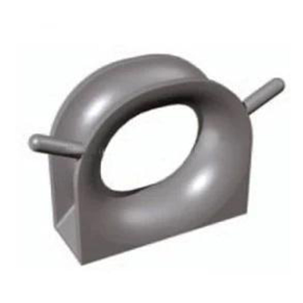
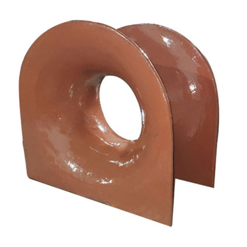
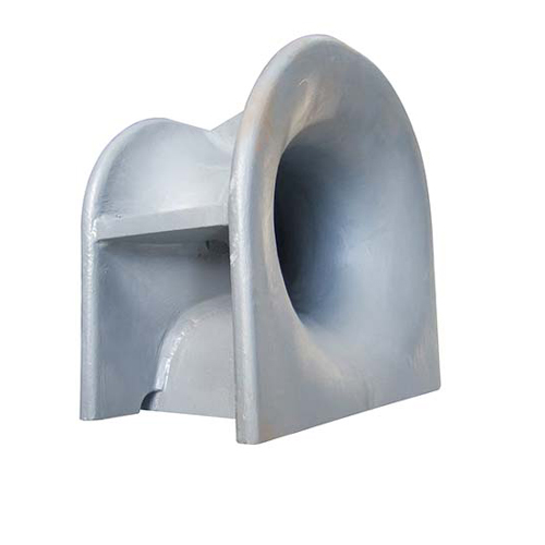
Dimensions of Type B – Bulwark-mounted mooring chocks
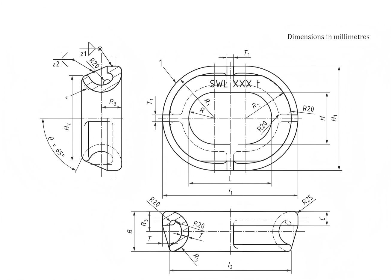
| Nominal size L×H (mm) | l₁ | l₂ | B | H₁ | H₂ | C | R | R₁ | R₂ | R₃ | T | T₁ | Welding leg lengtha | SWLb | Calculated weightc (kg) | ||
| Z₁ | Z₂ | kN | t | ||||||||||||||
| 250×200 | 450 | 398 | 154 | 408 | 327 | 57 | 100 | 200 | 174 | 78 | 26 | 20 | 8 | 8 | 353 | 36 | 48 |
| 300×250 | 516 | 460 | 168 | 466 | 387 | 60 | 125 | 233 | 205 | 85 | 27 | 24 | 8 | 95 | 491 | 50 | 83 |
| 350×250 | 582 | 520 | 177 | 482 | 395 | 65 | 125 | 241 | 210 | 90 | 29 | 25 | 9 | 10 | 589 | 60 | 100 |
| 400×250 | 652 | 588 | 193 | 502 | 412 | 70 | 125 | 251 | 219 | 98 | 34 | 32 | 95 | 13 | 736 | 75 | 145 |
| 450×250 | 734 | 662 | 213 | 534 | 433 | 77 | 125 | 267 | 231 | 108 | 41 | 36 | 125 | 145 | 981 | 100 | 215 |
| 500×250A | 812 | 730 | 237 | 562 | 447 | 82 | 125 | 281 | 240 | 120 | 41 | 36 | 125 | 145 | 1128 | 115 | 235 |
| 500×250B | 828 | 750 | 253 | 578 | 466 | 82 | 125 | 289 | 250 | 128 | 48 | 41 | 145 | 165 | 1373 | 140 | 266 |
| a: The welding method may be changed based on the same welding volume/strength. b: The SWLs shown are for reference only. These are based on the loadings as mentioned in Annex A. The “SWL” which is marked on the fitting may be adjusted depending on the actual loading conditions of the mooring rope under the agreement between the user and the manufacturer. c: The calculated weight (mass)is for reference only. | |||||||||||||||||
Key Features of ISO13713 Mooring Chock:
- High-Strength Construction: Made from marine-grade cast steel or ductile iron, ensuring durability under extreme marine environments.
- Corrosion Resistance: Optional hot-dip galvanizing or marine coating available for enhanced resistance to saltwater corrosion.
- Smooth and Fair Lead: The carefully designed profile minimizes wear and tear on mooring lines, extending their lifespan and ensuring smooth passage during mooring maneuvers.
- Fully Enclosed Design: Prevents rope escape and enhances line control, even under high tension.
- Various Mounting Options: Available in different mounting configurations (e.g., welded, bolted) to suit diverse deck arrangements and installation requirements.
- Easy Installation: Designed for welding directly to the ship’s hull or deck with clear mounting surfaces.
Optional Features: Depending on the manufacturer, may offer features like wear pads or specialized coatings for enhanced durability.
Applications of ISO13713 Mooring Chock:
- Cargo Vessels: Ensures safe mooring in commercial shipping operations.
- Tugboats and Workboats: Provides secure line handling for high-tension marine tasks.
- Naval Ships: Trusted for durability and reliability in defense marine fleets.
- Offshore Platforms: Used in fixed or floating offshore structures for anchor line routing.
- Fishing and Passenger Vessels: Adds safety and line integrity in vessels requiring frequent docking.
Why Choose Our ISO 13713 Mooring Chocks?
Our mooring chocks are engineered for performance, safety, and longevity. Whether you operate large cargo ships or small working vessels, the ISO 13713 chock is your trusted partner for secure mooring in all marine conditions.