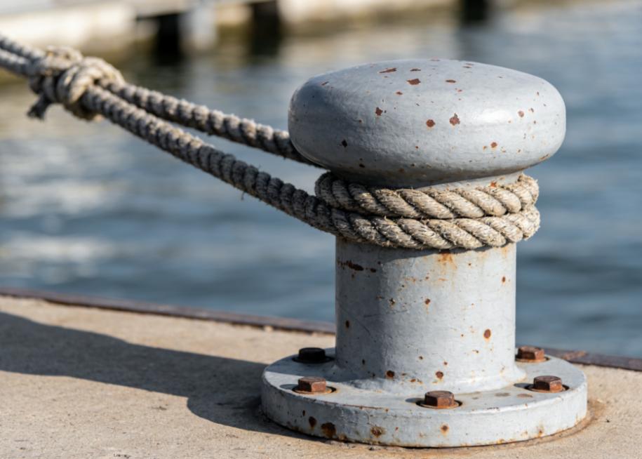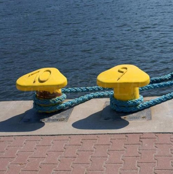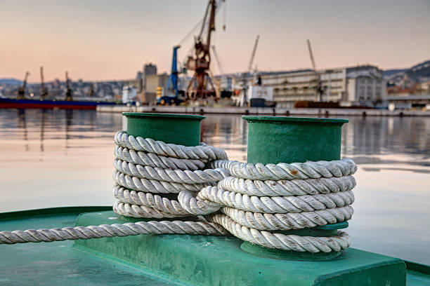
The core of sizing a mooring bollard is pretty straightforward. You figure out the maximum design load under your controlling case, then determine the required SWL, and finally verify that the bollard, its foundation, and its anchoring system all meet the design requirements.
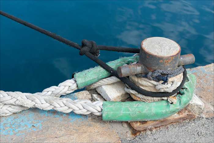
Why? Because a port mooring bollard isn’t just a standalone piece of steel. It’s the load-transfer hub that connects the ship’s mooring lines to the dock or to the vessel’s own deck structure.
If you just guess based on the vessel’s deadweight tonnage, you could end up with two problems. Oversized bollards waste money. Undersized ones might overload in extreme conditions, which could damage the mooring equipment or even the supporting structure. That’s a risk nobody wants.
This article walks you through five standard engineering steps. We’ll cover what inputs you need, how to derive environmental forces, how to decompose line tensions, and finally how to select the right mooring bollard and verify the foundation.
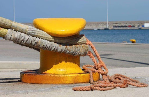
Step 1. Collect the Data for Your Mooring Bollard Calculation
Before you start any calculations, you have to gather complete field and vessel data. And don’t just look at the ship’s size. You need to treat the vessel, the lines, the environment, and the berth as one integrated system.
Start with the vessel’s characteristics: displacement, draft, exposed windage area, and underwater area. One thing to keep in mind: DWT gives you a rough idea of the ship’s scale, but it’s not a direct basis for setting the SWL of your mooring bollard. Don’t use it that way.
Next, look at your mooring lines and the arrangement. You need the total number of lines, how many share the same bollard, the minimum breaking load (MBL) of each line, the rope material and elasticity, and the pretension you plan to apply.
Then you’ve got geometry. Measure the vertical and horizontal angles of each line, plus the spatial distances between the ship’s fairleads and the bollard positions on the dock.
And finally, the environmental and berth conditions. Collect the design wind speed, current velocity, wave data, tide levels, and any other relevant conditions. If your applicable standard requires it, also consider extreme return periods for storms. Also note whether your berth is an open pier or a solid quay wall, because that geometry changes how currents and waves interact with the hull.
If you’re new to this, it’s helpful to first understand what a marine mooring bollard is and how it transfers line tension safely into the dock structure.
Step 2. Calculate the Environmental Forces
Once you have your data, the next step is to calculate the total external forces acting on the ship. When a vessel is moored in port, wind and current are the main continuous drivers. You need to quantify them using fluid mechanics.
Wind Force
Wind pushes against the exposed area above the waterline. The formula is:
Fwind = 0.5 × ρ × Cd × A × V²
where ρ is air density, Cd is the drag coefficient, A is the exposed windage area, and V is the design wind speed. Notice that wind force goes with the square of velocity. That means extreme wind conditions often become the controlling case for mooring loads.
Current Force
Current acts on the underwater hull in a similar way:
Fcurrent = 0.5 × ρw × Cd × Aw × Vc²
Here ρw is seawater density, Aw is the submerged area, Cd is the current drag coefficient, and Vc is the design current speed. Current force also scales with velocity squared, and the actual value depends on hull shape, flow direction, draft, and water depth.
Waves, Tide, and Dynamic Loads
Besides steady wind and current, you also have dynamic effects. Tide changes cause the vessel to rise and fall. Waves induce ship motions. Passing vessels create suction effects. Tug operations impose sudden pushes and pulls. All these contribute to dynamic mooring loads.
One important distinction: in port design, you often hear about berthing energy. That’s for sizing fenders, not bollards. Berthing energy is about impact during docking. It should not be mixed with steady-state mooring forces. Don’t just add them together.
Research on mooring loads shows that different environmental combinations can produce very uneven load distributions across your mooring system. Keep that in mind.
Step 3. Calculate Mooring-Line Tension and Load Distribution
Now that you have the total environmental force, you need to distribute it among the mooring lines and find the actual load on each bollard.
Line Angle Decomposition
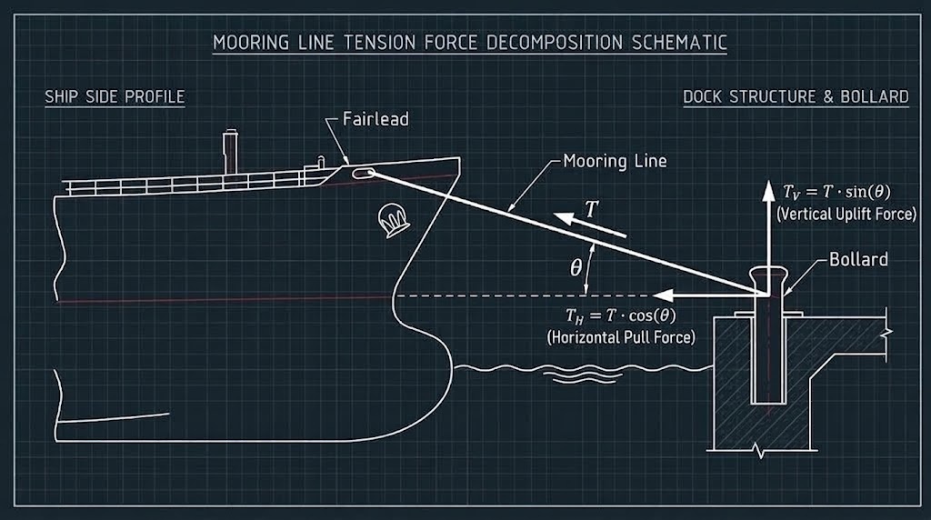
Mooring lines are rarely horizontal. Suppose a line makes an angle θ with the horizontal. The total tension T breaks into two components:
Horizontal component TH = T × cos(θ)
Vertical component TV = T × sin(θ)
The horizontal part resists the environmental forces to keep the ship in position. The vertical part adds uplift on the bollard and its anchors. That vertical load affects anchor bolts, the base plate, and the foundation’s pullout and combined capacity.
Load Sharing Between Multiple Lines
In practice, you can’t assume all lines share the load equally. Each line’s actual tension depends on its direction, pretension, axial stiffness, length, connection point, and the vessel’s movement. For your controlling case, you need to identify the line with the highest tension and the corresponding load on your marine bollards.
Check Different Load Directions
The vessel experiences forces from various directions. You must verify your bollard and foundation under longitudinal pull, transverse pull, vertical uplift, and combined oblique loads. The worst combination may not be the obvious one.
Step 4. Determine the Required Mooring Bollard SWL
After you’ve calculated the maximum design load on a single bollard, you can finally determine the required Safe Working Load. The chain goes like this: environmental forces → line tension decomposition → load distribution → single-bollard design load → required SWL.
When determining SWL, I wouldn’t recommend just applying a fixed safety factor like 1.5 or 2.0 mechanically. A better approach is to follow the international standard for your project (such as BS 6349 or PIANC guidelines), your project specification, and the specific design limit states you’re dealing with.
Also, remember that the bollard’s ultimate capacity depends heavily on the strength of the concrete foundation or deck structure underneath. Research on bollard and foundation capacity confirms that point.
To help non-specialists quickly grasp the key terms, here’s a summary table:
| Term | Full Name and Meaning | Why It Matters |
| SWL | Safe Working Load | This is the rated tensile capacity of the bollard. It’s the most important performance indicator when selecting a product. |
| MBL | Minimum Breaking Load | This is about the mooring rope, not the bollard. Don’t confuse SWL with MBL. |
| SLS | Serviceability Limit State | Covers normal daily operations and standard weather. The structure should not suffer permanent deformation. |
| ULS | Ultimate Limit State | Used to assess the structure’s capacity under extreme design conditions. |
| ALS | Accidental Limit State | Covers accidental events like line breakage or unexpected impact, providing additional safety margin. |
Step 5. Select and Verify the Right Mooring Bollard
Once you’ve done the calculations and have your required SWL, you move into product selection and engineering verification.
1. Match the Required SWL to the Bollard
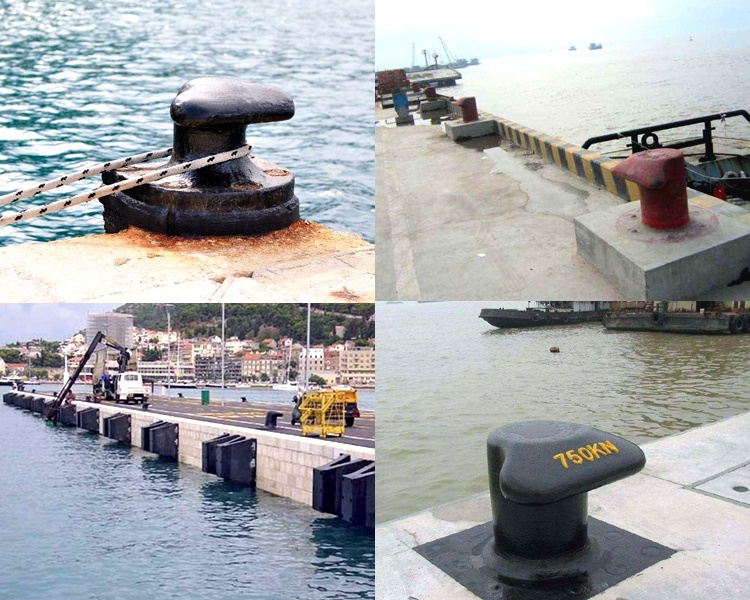
With your calculated SWL in hand, compare it against the available marine bollards on the market. Look at each model’s SWL, allowable load directions, structural form, material specifications, and any required classification society certifications or project documentation.
2. Choose the Bollard Type
Selection isn’t just about capacity. You also have to consider the port’s tide range, line angles, and available space. For a more detailed comparison, check our guide on marine bollard types.
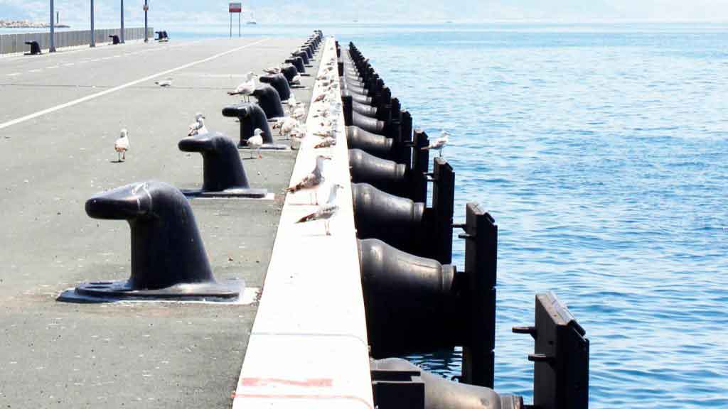
Common types and their typical uses:
- T–Head (Tee) Bollard: The T-shaped head provides plenty of space for lines. Good for larger approach angles and varied mooring arrangements.
- Double Bitt Bollard: The twin-post design makes it easy to separate multiple mooring lines. Common on both ships and docks.
- Staghorn Bollard: The special head geometry helps keep lines in place. Useful for specific angles and tight spaces.
- Kidney & Curved Dock Bollard: Compact forms that work well in confined dock areas.
- Cruciform Bollard: The cross shape offers multiple line directions. Applicability depends on installation position and load requirements.
3. Verify the Foundation and Anchor System
The bollard’s own strength is only part of the equation. After you select it, you have to verify the foundation thoroughly. Proper mooring bollard installation ensures that the bollard, anchor bolts, and support structure act as a unified load-bearing system.
In engineering checks, you typically need to examine these key elements:
- Anchor Bolts: Check the number, material grade, shear strength, and pull-out resistance.
- Base Plate: Ensure the plate is thick enough to spread the concentrated stress evenly.
- Welds and Connectors: Check for stress concentrations or weld defects.
- Grouting Layer: Make sure there are no voids under the base plate so that compressive stress is uniform.
- Quay Concrete Structure: Verify the concrete’s local punching shear and tensile breakout capacity.
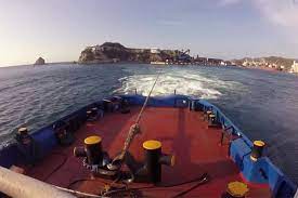
- Under–deck Reinforcement: For deck-mounted bollards on vessels, check the stiffeners and supporting structure underneath the deck.
If there’s any error in foundation verification or load assessment, it can easily lead to serious bollard failure under severe conditions.
Conclusion
Mooring bollard capacity isn’t a one shot calculation. Gather vessel and berth data. Calculate wind and current forces. Convert to line tensions—spatial angles are non negotiable. The maximum load on a single bollard gives the required SWL. Select the bollard type. Verify the foundation and anchors.
For projects with a specific SWL requirement or custom installation, Boomarine supplies a full range of marine bollards in different types and specifications. Customisation is also available. The right configuration can be confirmed based on your project needs.